POSTED BY: STUART KEMP, DALROAD
Many engineers, well versed in the art of constructing industrial panels and installing them into the most complex of systems are still finding their profits eaten into by having to return to site to correct drive-related interference and other electro-mechanical compatibility (EMC) problems.

Most if not all radio frequency interference problems created due to operating variable speed drives (VSD’s) can be avoided by following good engineering practice when designing the layout of an enclosure and then again during installation of the associated cabling and equipment in the field.
Modern general purpose PWM type VSD’s use power semiconductor (IGBT) technologies that are designed to switch hundreds of volts at anywhere between a couple of amps to several hundreds of amps with a typical switching rate of between 2kHz and 15kHz. Therefore each 20mS cycle of a typical 50Hz sin wave can be created by up to 15000 switching operations. The super-fast transition times between devices switching off and devices switching on (typically a few micro-seconds) can lead to radio frequency disturbance of other equipment.
In a poorly designed installation, each time a device operates there is a good chance that high frequency currents will flow through all kinds of hidden paths and can ultimately affect the performance of sensitive equipment installed nearby.
Some emissions from VSD’s will be air-borne but will naturally attenuate very quickly close to the VSD casing and more often than not cause fewer problems per se. Practically, the biggest problems are usually from conducted emissions which use the actual cables connected to the VSD as a propagation path. Like radiated emissions these also have to be controlled and should be kept within the limits set out in various IEC and European Standards – for example the ‘Power Drive Standard’ – EN61800-3 and its relevant sub standards to conform to the European EMC Directive 89/336/EEC.
The first step in ensuring interference-free operation is to choose a variable speed drive that has some kind of filtering which can be in the form of an integrated filter built inside the drive or an off-board type. There are many types of EMC filter and in case of using a low attenuation type (low cost, single stage) much more supplementary work may be necessary elsewhere to improve its limited performance.
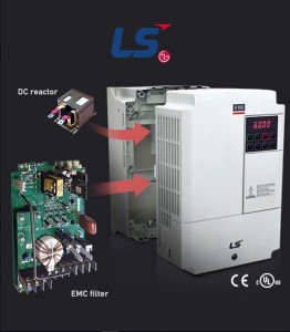
Figure 1 shows an LS Industrial Systems S100 general purpose VSD with an integrated DC reactor and EMC filter – useful when space in the enclosure is at a premium.
The next thing to consider is where on the enclosure back plate the VSD will be mounted and the route the power and control cables will take before exiting the enclosure. It is often advantageous to mount the drive(s) near the top of the enclosure and as far away as possible from any sensitive equipment, i.e. PLC’s, HMI’s, and any other controllers utilising sensitive analogue and/or digital signals.
Make sure that the mains power input cables to the drive are not routed alongside or close to the highly RF contaminated motor output cables. Keep them at lease 300mm apart where they have to run parallel to each other.
It is also important that control cables in and out of the drive are run completely separate to power and motor cables, and cable ties should never be used to loom any cables associated with a drive.
Most back plates of enclosures are unpainted nowadays as the enclosure manufacturers realise the potential of using the back plate as a powerful RF grounding plane. Without a painted finish many types of equipment with alloy heatsinks or feet for example can be mounted metal on metal giving the best supplementary electrical grounding and at the same time offering highly beneficial EMC performance.
Where the incoming power cable enters the enclosure it can have real EMC benefits to securely connect the earth conductor to the back plate close by, then reference the VSD’s own earth connections along with the earth connections of other equipment in the enclosure directly to that point in a ‘star’ configuration.
Next we must consider the cable between the enclosure and the motor. It is all too often the case that installers may use a simple unscreened 4-core flexible cable or even single cables running inside trunking or plastic conduit, for example, to connect the motor to the enclosure where the drive is installed. While this type of cable may be electrically adequate for operating the motor at the chosen operating frequency, it is a potential banana skin when EMC related issues are taken into account.
Due to the effect of cable capacitance, stray current paths between conductors and ground can present an easy propagation route for high frequency emissions. Coupling of these currents can also occur between unshielded conductors of different circuits. Further, motor winding insulation is useful only against fundamental power frequencies and offers no barrier to high frequency switching currents which can simply pass straight through the insulation onto the metal frame of the motor. A correctly earthed motor could then provide a current path directly to the earthed star point on the low-voltage side of the supply transformer. This could have significant and detrimental effects to other users fed from the same transformer in terms of interference with equipment they are using.
So what type of cable is the best option when connecting a motor to a VSD or enclosure containing a VSD(s)? The answer is always the same – armoured or screened types (as long as it conforms to national standards and regulations) are always the wisest choice.
The armour or screen must be connected to a good electrical earth at both ends, i.e. at the enclosure and at the motor. If a local isolator is installed close to the driven machinery it is essential that the screen has electrical continuity across that device. This will provide a low-impedance return path for the high frequency currents and form a protective ‘Faraday Cage’ around the conductors. The screen will also help the EMC filter in the VSD to operate correctly and generally clean up the system earth so it is free from or carrying less HF current.
There are certain applications where using a fully shielded motor cable with the shield grounded at both ends is very difficult if not impossible to achieve; submersible borehole pumps, gantry cranes and elevators for example. In these situations special measures are called for and the VSD supplier should be consulted for best practice. Often the use of an appropriate Sine Filter installed at the VSD’s output terminals is recommended and these are especially useful when the motor cable is unavoidably very long.
If the motor cable can be kept as short as practically possible, a reduction in the cables’ capacitance will be seen, hence leakage currents which cause interference will also be reduced. This is not always practical but with the rise in popularity of higher IP rated drives it is now possible to mount the VSD directly to a wall, pump skid, the leg of a conveyor or on the side of an air handling unit for example and so completely decentralising the installation and often giving problem free commissioning in terms of EMC.
Most modern VSD’s also give the user / installer access to the IGBT switching rate, commonly referred to as ‘switching frequency’ or ‘carrier frequency’. The user can adjust the switching frequency between factory-fixed low and high limits. If appropriate to the application the installer can reduce the switching rate which may make the motor emit an audibly different sound but may also have the benefit of reducing conducted emissions still further and having the added bonus of reducing the heat losses from the VSD(s) in the enclosure.
By following these few simple EMC rules at the enclosure design stage and again during the system installation stage it is possible to minimise or completely negate RF interference with other equipment often found during the final commissioning period.
The nightmare scenario of having to return to a job many times to analyse and retrospectively correct common EMC problems caused by incorrectly installed VSD’s can be entirely avoidable and profits from the project can be maximised.
For further information on S100 VSDs visit https://www.dalroad.com/product/s100/ or contact us at [email protected].